Aerial Recon
Final Report
-
Software Engineering Studio
Professor Jane Huang
Spring 2016
James
Evarts
Christopher
Lenard
David
Messer
George
Opira
Zakriya
Rahman
Clarissa
Ryan
Department of Transportation Application
Architecture and Construction Application
Aerial Recon is an aerial imagery gathering platform that enables users to gather aerial information via a mobile platform. Aerial reconnaissance, as a way of gathering aerial imagery, is used in a variety of contexts and industries today. Whether aerial imagery is used as a way to gather critical intelligence on an enemy position during a military operation, to perform an initial search on a search and rescue mission, to gather agricultural data for a farmer looking to improve his crop yield, or as a way to simply survey and discover patterns about an area, aerial reconnaissance is a valuable service with a number established use cases.
In this project, a safety critical context of aerial reconnaissance was considered in order to guide development. This does not imply that the system does not have broader applications for other use cases but was chosen as the guiding context for the design and development of the application.
Safety is considered paramount in the development of this system and affects the design and development in two ways. First, the system must perform reliably and accurately because professionals that depend on the information gathered use that information for a variety of missions that have significant safety implications. For example, a search and rescue team may depend on the aerial information gathered from the system in order to identify the location of a missing person. This information is critical to the rescue of the missing person and thus the Aerial Recon system must reliably provide that information. Second, the system must perform its tasks in such a way that it does not in itself create further safety risks. A drone that has a hardware failure may not only not perform the tasks of gathering aerial imagery, but it may also fall and hurt someone. The second facet of safety consideration, “do no harm”, must be considered in the design and development to ensure that the system does not pose new threats to safety. This issue is discussed further in the safety analysis.
In this report, the following are detailed:
· initial product requirements to identify the explicit guiding forces for the system,
· a safety analysis detailing all hazards, faults, mitigating requirements, and a safety case,
· the architectural design of the system,
· testing methods and results,
· user studies explaining the various user contexts and user stories for the system,
·
and suggestions
for future work identifying areas for improved safety and improved
functionality.
To guide the development of the Aerial Recon system, a necessary vision and goals needed to be established. After researching the predominant use stories for aerial reconnaissance, a baseline vision was created that encapsulated those user stories into a minimum viable product. For the minimum viable product, it was determined that the system should allow a user to access an interface remotely, specify a geographic coordinate to send the drone to, dispatch a drone, receive that imagery and render it in the client user interface. These functional attributes of the system would be considered alongside non-functional attributes, including safety and reliability.
The following goals were established to guide the development of the system. In the context of the Scrum process, the goals below represent the “epics” for the product. It is important to note that these were the initial high level goals for the system and formed the basis of the product backlog. Various goals were prioritized for each two-week sprint. As such, not all goals were accomplished during the development of the product.
|
Goal ID |
Goal Description |
|
G1 |
The system shall send a drone to a point of interest and capture aerial image |
|
G2 |
The system shall capture an aerial image of a location |
|
G3 |
The system shall render reconnaissance imagery in a map on a user interface. |
|
G4 |
The system shall transmit imagery in real time. |
|
G5 |
The system shall compile series of images into a stitched composite image |
|
G6 |
Provide a user interface that allows the user to manually control the flight path of the drone in real time |
|
G7 |
Record path and progress of drone during flight |
|
G8 |
(Accuracy) The drone must ensure correct GPS positioning and transmit information accurately. |
|
G9 |
(Safety) The drone must operate without harming anyone |
|
G10 |
(Safety) The drone must avoid all obstacles |
|
G11 |
(Safety) The drone must fly within legal airspace |
Each of the epics above was then further broken down into specific user stories. These user stories were broken down into further requirements using the EARS Requirements format from IBM. These were documented in the Atlassian JIRA system, a tool used for identifying all “issues” and managing the software development process.
|
|
|
|
Establish Trace Links as per the Traceability Information Model |
|
|
Establish Trace Links as Traceability model |
|
|
When a user navigates to the service website, the server shall send the client interface. |
|
|
When a user starts a new ‘mission’, the server shall check for available drones. |
|
|
If a drone is available, the server shall inform the user of the available drone. |
|
|
If a drone is not available, the server shall provide an estimate of time until a drone is available. |
|
|
When a user selects a point on the map, the base station shall send the GPS coordinate to the drone. |
|
|
The drone shall constantly monitor its remaining flight time against the “flight time to return to base”. |
|
|
If the remaining flight time is 5 minutes longer than the distance to home base, the drone shall return home. |
|
|
While in flight, the drone shall maintain an altitude below 400 feet / ~120 meters. |
|
|
While in flight, the drone shall detect obstacles in its path. |
|
|
While in flight, the drone shall avoid any areas with people. |
|
|
If the drone detects an obstacle, the drone shall adjust its path to go around the obstacle. |
|
|
When receiving a new waypoint, the drone shall adjust its flight path and fly to the new waypoint. |
|
|
Video will be transmitted to the base station for processing. |
|
|
When the server receives an image, it shall render the image in the client view. |
|
|
If the drone loses communication with the base station, the drone shall return to its base station position. |
|
|
When the drone receives a flight plan, it shall initiate its flight sequence. |
|
|
When the drone changes position, it shall update the base station with its new coordinates. |
|
|
When images are rendered on the UI map overlay, the client interface shall allow users to tag objects. |
|
|
When a user makes a request on the web application, the request is sent to the server. |
|
|
When a drone takes a picture, the image must be persisted in a database. |
|
|
The server shall interact with the drone using MAVProxy. |
To ensure that the system is “safe”, a safety analysis was performed to identify the potential safety issues that could arise and identify ways of mitigating those risks. The safety analysis includes a threat model, identifying the potential human threats to the system, hazards that may hinder the system in achieving system goals, faults identified in the system, mitigating requirements that attempt to resolve hazards or threats, and an overview of the safety case.
Threat Model
There are a variety of threats that are posed to the system. Threats are any security vulnerability posed by an external force. In this case, the threat modeling is anthropocentric where actors have a specific action and purpose. In the case of aerial reconnaissance, a number of actors do emerge as potential sources of threats. For example, in military aerial reconnaissance, enemy forces would not want the operating unit to be successful in gathering aerial intelligence. By employing a variety of tactics to disrupt the system, enemy forces would effectively render the system useless. These and other threats are explored in the threat model below. The threat model describes the threat type, the target of the threat (defined as a part of the Aerial Recon system), the actor – or who would carry out the attack, the action – what specific steps would be taken to threaten the system, the purpose or motivation for those actions and the expected result of the actions.
|
Threat001 |
|
|
Threat Type |
Indirect attack - Radio Communication
Jamming |
|
Target |
Communication |
|
Actor |
Hostile forces |
|
Action |
Actor determines and ‘jams’ electromagnetic communication between
drone and base station |
|
Purpose |
To render the drone inoperable |
|
Result |
The drone becomes inoperable by the base station |
|
ThreatID |
Threat002 |
|
Threat Type |
Technological Attack - Altered Flight
Plans |
|
Target |
Waypoint System |
|
Actor |
Hostile forces |
|
Action |
Actor sends altered flight plans to make the drone fly to
unintended places |
|
Purpose |
To give inaccurate aerial
reconnaissance information |
|
Result |
The system is unable to fly to intended targets to capture
aerial reconnaissance images |
|
ThreatID |
Threat003 |
|
Threat Type |
Technological Attack - DDoS Attack |
|
Target |
Application Server |
|
Actor |
Hostile forces |
|
Action |
Actor sends a large amounts of requests to server overload it. |
|
Purpose |
To prevent a drone pilot from
communicating with the server. |
|
Result |
Drone pilot is unable to send requests to server and therefore
the drone. |
|
ThreatID |
Threat004 |
|
Threat Type |
Technological Attack - Navigation
Manipulation |
|
Target |
Navigation system |
|
Actor |
Hostile forces |
|
Action |
Actor impacts the drone’s navigation system so it receives
incorrect GPS coordinates |
|
Purpose |
To cause the drone to lose its
navigation |
|
Result |
Drone is lost and may not return to the base station |
|
ThreatID |
Threat005 |
|
Threat Type |
Physical Attack - Shooting down drone |
|
Target |
Drone |
|
Actor |
Hostile forces |
|
Action |
Actor shoots down drone using ballistics |
|
Purpose |
To render the drone inoperable |
|
Result |
Drone is damaged and inoperable |
|
ThreatID |
Threat006 |
|
Threat Type |
Physical Attack - Camera Vulnerability |
|
Target |
Camera System |
|
Actor |
Hostile forces |
|
Action |
Actor floods camera with infrared light |
|
Purpose |
To diminish the quality of drone
imagery |
|
Result |
Aerial imagery is distorted and unusable |
|
ThreatID |
Threat007 |
|
Threat Type |
Technological Attack - Enemy Access |
|
Target |
Web System |
|
Actor |
Hostile forces |
|
Action |
Actor gains access to system through client login and password |
|
Purpose |
To exploit technological
infrastructure and install botware |
|
Result |
Enemy monitoring and disruption of services |
|
ThreatID |
Threat008 |
|
Threat Type |
Indirect attack - Sabotage |
|
Target |
Drone system |
|
Actor |
Hostile forces |
|
Action |
Actor gains access to drone manufacturing facilities or product
parts |
|
Purpose |
To exploit technological
infrastructure, install botware and compromise
product quality |
|
Result |
Enemy monitoring and disruption of services |
Hazards
Hazards are any threat that are posed to the system that do not fall within the anthropocentric threat model. A hazard is considered any event that could cause system failure or hinder the system from achieving its goals.
Power Loss
If the drone runs out of power, the system will fail because the drone will no longer have the energy resources available to maintain operable flight modes. This would mean that the drone could potentially lose power, thus causing the propellers to stop creating lift causing the drone to crash to the ground.
Obstacle Collision
Other obstacles pose a hazard as the drone could run into the during operation. For instance, if a drone flies along a flight path where a building is in the way, it could run into the building potentially causing damage to the building, damage to the drone (in the event that it falls and crashes) or, in a worst case scenario, could cause harm to life if the drone falls onto a person.
Precipitation
Precipitation poses a hazard to the operation of the drone because any water damage would inevitably affect the onboard electrical system. This could create an electrical failure and cause the drone’s subsystems to fail.
High Winds
High winds are a hazard to drone flight since the drones are not designed to operate under heavy wind conditions. In such conditions, the drone loses control of its operation which may result in a failed operation or potential damage to the system.
Available Light
One dependency of the aerial reconnaissance system is available light. Since the camera system captures visible light frequencies, images can only be captured during times where visible light is available. Given this constraint, drone operation is only successful when operated during the daytime.
Faults
Faults are safety issues discovered in the testing of the system. A few faults were discovered during the process of developing and testing the system. One fault is that users can enter in any geographic location in the world and submit it. Because the system does not check to see if the geographic coordinate is within a reachable region for the drone, the drone will begin its mission, go as far as it can, then return to the base station when it senses that it is about to run out of batteries. This is considered a fault because a user should be given feedback about whether or not the mission is possible before the time of dispatch. Other faults include the fact that the system does not detect obstacles and so can cause issues. To mitigate the risk, test flights were only performed in controlled areas where no obstacles could cause a fault to occur.
Mitigating Requirements
Mitigation is a strategy used to manage a system toward its desired state, either by reducing unwanted impacts or increasing desired impacts. In order to mitigate the risks posed by threats, hazards and faults, the following mitigating requirements were identified.
· Because the system may run into obstacles at low altitudes and has no current way of detecting obstacles, the system shall fly at an altitude of 300 feet.
· Because the system is not conclusively safe, the system shall fly in unpopulated areas to reduce the risk of harming human life.
· Because the drone, as a subsystem, is incapable of handling winds in excess of 5 mph, the system shall only be flown under wind conditions of less than 5 mph.
· Because the drone may fail in precipitation due to water damage, the system shall only be flown when there is no precipitation.
Through the employment of the mitigating requirements identified above, the risks posed will be mitigated.
Safety Case
The Aerial Recon team used FMEA methodology to performed analyses of the Aerial Recon system to identify potential hazards, risks and the effects of those failures to safety of system developers, system test personnel, and the general public. For every potential failure, the team designed preventive solutions or mitigating mechanism. When possible, these mitigating factors were integrated it into the system design, architecture and implementation in order to prevent the failure from happening, or mitigate the effects/impacts of a failure to a safe level of tolerance should it occur.
Tests cases were also developed to test the effectiveness of these preventive and the mitigating solutions to the potential failures identified by the project team. The results from these test cases would then be evaluated to asses them against the safety requirements and system behaviors expected from these tests. These test cases were to be performed during the second phase of the project when the project team was implementing the actual project design solutions for the whole system.
During the second phase of the project, the project team did implement some safety assurance cases and tested some of the preventive and mitigating solutions to these potential failures. However, the team was unable to implement some of the solutions, and hence, could not test them against the expected outcomes. This is because the team was not able to complete the project entirely due to time constraints.
The result of our assurance cases are divided in to two parts. The first part shows the safety assurance cases which were actually implemented and tested on the system or parts of the system. The second part of the safety assurance cases indicates the cases which the development team did not actually implement, and never tested on the system or components of the system – they are tests for future implementations when this project is being brought to total completion by another project team which will continue with this project from where we have stopped at the moment.
Assurance
This is the confidence that the system will work as intended within the limitations of its design requirements while mitigating all the potential hazards and safety issues that may arise during system normal or abnormal operation conditions. Confidence Assessment: This confidence in the system is assessed qualitatively through extensive tests designed to mitigate potential hazards arising from the use of the system under all possible conditions of normal and abnormal operations of the system.
The two main approaches used to structure a safety assurance case are to Identify safety requirements, and show that these safety requirements are satisfied and to Identify safety hazards, and show that they have been eliminated or satisfactorily mitigated. These approaches maybe applied in conjunction with each other– meaning to have met safety requirements is to show that potential hazards have been eliminated or mitigated. The two approaches play important roles in developing safety assurance case (From Assurance Case Practice Text).
Assurance case
Methodology
Initially potential safety hazards were identified by the project team through Failure Modes and Effects Analysis (FMEA). The project team developed and incorporated safety requirements into the overall project design requirements, and tests are then designed, and performed to evaluate the effectiveness of the safety modes failures incorporated into the project design to mitigate hazards.
The project team main focus of the Assurance cases are those potential hazards identified in FMEA, and how they are effectively mitigated. These were done through tests evaluation and test results analysis. The project team also got assurance from the drone manufacturer that all the drone parts met safety requirements regarding public health with respect to toxicity of materials incorporated into the drone (manufacturer’s documents that came with the drone). These give the project team confidence to conclude that the drone can fly safely as per design requirements and other safety considerations.
Assurance Case: The Aerial Recon system is safe.
Implemented Safety Cases and Test Cases
1. Potential Hazard:
Drone Collides with an Obstacle
Hazard Mitigation:
· Drone checks its altitude to make sure it can fly down or up to avoid collision
· Drone paths and coordinates are constantly monitored from base station to identify potential drone nearby current drone
· Drone Is only flown in locations with limited obstacles
Test Results:
· Drone was able to monitor its altitude, and could fly down or above current altitude
· Drone flies at a minimum altitude above trees and buildings entered into drone system
· Drone was able to send its current location/coordinates to the base station via radio link
· Drone can store its current location and other data in case of communication failures and resend them when it re-established communication with the base station
Test Pitfalls:
· Sensors can fail and inaccurate data could be sent from the drone to the base station
· Altimeter or altitude sensor failure could occur and wrong altitude sent
· Incorrect altitude or sensor logics in the algorithm for calculating altitude, or locations
· Communication failure between the drone and the base station due to radio failure
2. Potential Hazard:
Drone parts contain dangerous metals or materials (e.g. Lead, mercury, zinc)
Hazard Mitigation
· Drone manufacturer’s documents do not indicate the existence of dangerous materials
· Manufacturer’s documents indicated that the drone was manufactured according to public safety requirements and internationally accepted best manufacturing standards
Test Results:
· Project team relied on vendor’s documentation to ensure the product meet safety standards
Test Pitfalls:
· Regulators did not validate the manufacturer’s claim
· Manufacturer’s document about material safety may not be 100% accurate (acceptable amount of hazardous materials vs actual amount)
3. Potential Hazard: Drone Flies Away
Hazard Mitigation
· Distance-monitoring logic is used to monitor how far the drone is from the base station
· Auto return-to-base logic is incorporated into flight-logic so that once the target distance is reached or communication is lost with the base, drone can return to base
· Drone caries GPS – locator to help the team to recover drone in emergency situation
Test Results
· Drone location and coordinates in flight were correctly sent to the base station
· Drone successfully auto-returned to the base when radio communication was lost
Test Pitfalls
· Logic errors in distance –to-target calculation could incorrectly activate the “hijacked-mode” and disabling the drone unnecessarily
· Auto-return to base may fail, and the drone could potentially get lost in the event there is loss of communication with the base
· GPS failure may occur due to low battery, and the drone may not be located at all
4. Potential Hazard:
Unauthorized access of system
Hazard Mitigation:
·
Implemented required authorization to access web
application
Test Results:
·
Attempts to log in without access credentials
failed
Test Pitfalls:
·
Brute force attacks were not attempted
·
Other “hacking” techniques were not tested
Architectural Design
In order to develop a system that meets the necessary requirements, the team worked to architect a baseline system that could achieve the aforementioned goals. An initial use case diagram was sketched out as follows:
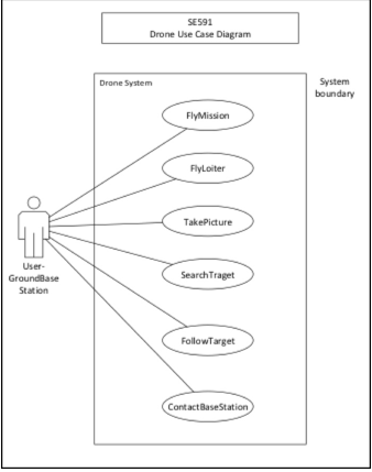
Initial Use Case Diagram for Aerial Recon System.
The system was designed with the following quality attributes:
· Safety
· Reliability
· Availability
· Accuracy
The system Is designed after a Model – View – Controller architectural pattern. In this model, the “view” is the user interface that the user interacts with, the “controller” is what allows the user to send specific commands to the drone via the exposed interface, and the “model” includes the underlying objects and services provided. The view is developed as an HTML page that renders a map utilizing the Google Maps API. The Google Maps API provides a functional interface that allows a user to select a geographic point on a map which is then processed as a geographic coordinate consisting of latitude and longitude positions. This coordinate is then passed to the Azure cloud server using a PHP script that passes the coordinates to a Python script that then communicates with the drone using the MavProxy protocol library developed in Python.
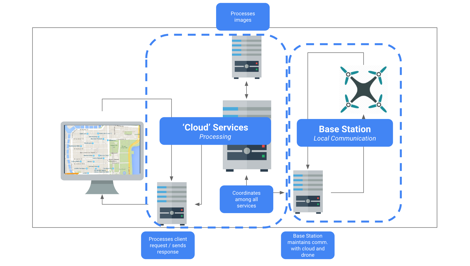
Initial high level architectural diagram.
This interface - client view with a server running PHP and making calls to a drone via Python scripts - establishes a baseline communication between the client and drone. In essence, this establishes a drone service which allows the system to dispatch a drone to a particular geographic location. Once the drone is dispatched, a video streaming service is opened, transferring data from the drone’s onboard camera to a video stream. This video stream is then captured and displayed to the user. Images are rendered in a client-side map.
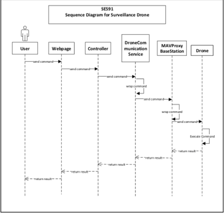
Initial Sequence Diagram for Aerial Recon system.
Testing is an essential part of the software development process. By testing a system, it is possible to ensure that it behaves at is supposed to (and does not behave in ways that are not intended). With a safety critical application, it is essential to conduct testing in order to provide evidence for the safety case as well.
Test Design
In order to test the Aerial Recon system, a variety of acceptance tests were defined according to the system goals. It should be noted that due to prioritization, not all goals were attempted or achieved. As such, the acceptance tests that did pass reflect those that were a higher priority for the team during the development process. For example, the workflow where users have to confirm the reconnaissance point was prioritized lower than rendering images in the client interface.
|
Test ID |
Test Name |
Test Steps |
|
T001 |
User: Landing page |
1. User navigates to
http://airrecon.northcentralus.cloudapp.azure.com/ |
|
T002 |
User: register |
User clicks on menu bar |
|
T003 |
User: log in |
User navigates to
http://aerialrecon.northcentralus.cloudapp.azure.com/ |
|
T004 |
User: Select recon point |
User selects point on Google Map |
|
T005 |
User: Confirm recon point |
System confirms point with user |
|
T006 |
User: Start mission |
System confirms mission start |
|
T007 |
Server: Arm drone |
Server arms drone with python script |
|
T008 |
Server: Dispatch drone |
|
|
T009 |
Drone: Receive waypoint(s) |
When server sends waypoint, drone receives waypoint |
|
T010 |
Drone: Liftoff |
After drone receives waypoint, drone starts liftoff sequence |
|
T011 |
Drone: Fly to point |
When drone completes liftoff sequence, drone flies to waypoint(s) |
|
T012 |
Drone: Send images |
Drone sends imagery while in flight |
|
T013 |
Server: Receive images |
When drone sends imagery, server receives image files |
|
T014 |
Server: Render images in client UI |
When server receives image files, server renders images in Client
UI |
|
T015 |
User: View imagery |
While drone is in flight, user can see imagery |
Test Results
The system tests were performed and all tests passed with the exception of T005: User: Confirm recon point. This test failed because there was no development effort applied to achieve the goal. As such, this particular goal was not achieved.
|
Test ID |
Test Name |
Test Steps |
|
|
T001 |
User: Landing page |
1. User navigates to
http://airrecon.northcentralus.cloudapp.azure.com/ |
ü |
|
T002 |
User: register |
User clicks on menu bar |
ü |
|
T003 |
User: log in |
User navigates to
http://aerialrecon.northcentralus.cloudapp.azure.com/ |
ü |
|
T004 |
User: Select recon point |
User selects point on Google Map |
ü |
|
T005 |
User: Confirm recon point |
System confirms point with user |
û |
|
T006 |
User: Start mission |
System confirms mission start |
ü |
|
T007 |
Server: Arm drone |
Server arms drone with python script |
ü |
|
T008 |
Server: Dispatch drone |
Server sends waypoint to drone |
ü |
|
T009 |
Drone: Receive waypoint(s) |
When server sends waypoint, drone receives waypoint |
ü |
|
T010 |
Drone: Liftoff |
After drone receives waypoint, drone starts liftoff sequence |
ü |
|
T011 |
Drone: Fly to point |
When drone completes liftoff sequence, drone flies to
waypoint(s) |
ü |
|
T012 |
Drone: Send images |
Drone sends imagery while in flight |
ü |
|
T013 |
Server: Receive images |
When drone sends imagery, server receives image files |
ü |
|
T014 |
Server: Render images in client UI |
When server receives image files, server renders images in
Client UI |
ü |
|
T015 |
User: View imagery |
While drone is in flight, user can see imagery |
ü |
There are a number of different industries that perform aerial reconnaissance as a way to gather intelligence. These include military, agriculture, search and rescue, law enforcement, transportation, construction, marketing, and film. The following will describe the applications of an aerial reconnaissance system in a variety of use contexts.
Military Application
In the military, operations and strategy can hinge on the intelligence gathered. Knowing enemy positions, size, resources available, supply flows and movements can be an invaluable asset in developing strategies, operations, and tactics. Today, much of this information is gathered through the deployment of both manned and unmanned vehicles. By creating a lightweight, portable aerial intelligence gathering system, it is possible for mobile units to gather intelligence quickly and readily without the need to dispatch a large aerial reconnaissance mission.
Agricultural Application
Agriculture ventures depend upon successful yield to support business revenues. Knowing the health of your crop is essential to identifying steps to successfully manage it. Today, some farmers will employ a local pilot to conduct flyovers to take videos of plots of land. This is a costly endeavor and is undertaken rarely due to its cost. By allowing farmers to deploy drones in a “drone-as-a-service” model, information about their crops can be gathered for less cost. This means that farmers could gather more information throughout a season and thereby manage their crop toward higher yields. There are emerging “drone-as-a-service” businesses that are targeting this specific market, such as in North Dakota.
Search and Rescue Application
Search and rescue operations are time-sensitive missions where lives are at stake. In a search and rescue operation, it is essential to gather information. Typically, a search and rescue operation will begin by limiting the scope of a search – where was the person last seen? Where did their plane crash? If a relative location can be established, a search team can begin their search efforts. Often, this is accomplished through a flyover in a small private plane. A spotter will scan the landscape for any visual indicator of the missing person. If any signs are identified, the area is explored further. This approach can be used with drones as well. If a targeted area is identified, one or more drones can be dispatched to the area. The drones can fly at altitude, scanning for any visual indicator of a missing person. If any visual indicator is detected, the drone can descend on the spot to investigate further. This approach could even enable a search and rescue team to give a missing person “hope” and instruct them to stay in the current location while a team is dispatched. There are significant opportunities to increasing the likelihood of finding a missing person through the use of a “swarm” aerial intelligence gathering approach.
Law Enforcement Application
Law enforcement employs aerial reconnaissance tactics for three key activities: surveillance, suspect tracking, and speeding monitoring. Law enforcement agencies employ surveillance tactics (when court-approved) as a way to gather information about a suspect’s activities and location. The use of a drone to collect information could be a simple way for agencies to gather information around the clock with less of an investment than flying a manned aircraft. It would also enable agencies to detect any activity and respond, rather than employing detectives to wait and watch for activity.
When a suspect is “on-the-move” or fleeing a crime scene, aerial intelligence is gathered to follow their movements. This may be used for a suspect fleeing by foot or vehicle. The Aerial Recon system would be valuable in cases where suspects are fleeing by foot given constraints on the speed of a drone. This system, though slower than approaches such as a helicopter, may actually be more valuable as it allows for a more nimble flight pattern through urban areas.
One other application of aerial intelligence is speed monitoring. Agencies use aircraft to monitor vehicle speeds as a way to enforce speed limits. This approach can be costly and as such is only employed in cases where a significant number of speeding tickets will be given. A drone-based speeding enforcement system would allow agencies to gather aerial information on speeding vehicles with less cost.
Department of Transportation Application
The Department of Transportation gathers information about traffic as a way to understand the interaction between traffic and infrastructure. This information is gathered with a number of inputs including aerial surveillance. Visual imagery can provide more insights into traffic patterns as opposed to sensors that may count the volume of traffic in only one location. By allowing the Department of Transportation to deploy a drone to gather aerial imagery, traffic patterns can be studied at a reduced cost.
Architecture and Construction Application
Industries that depend on site surveys utilize aerial imagery to create these base documents. The aerial recon system could be of value as a way to quickly gather aerial imagery at a fraction of the cost of other methods.
Marketing Application
Businesses that create marketing materials can incorporate images or video footage from a drone into various artifacts. This can be used to showcase a business location, a travel destination and so forth.
Film Industry Application
Aerial shots in the film industry can be costly, especially when multiple takes are needed. By using the aerial recon system, film crews can quickly and efficiently gather video footage without the cost of large operating equipment, computer-graphics, or manned aerial footage.
The Aerial Recon system as it is developed today is a “minimum viable product” that achieves the base functionality of allowing a user to specify a geographic location to gather aerial imagery from, dispatches a drone, and returns the relevant imagery. There are a significant number of areas that can be developed in order to further the safety and usability of the system.
Improve Safety
Safety is a critical aspect of the Aerial Recon system. There are a number of areas that could further enhance the safety of the device in its performance of tasks.
Reduce Potential Collisions
It is essential that the Aerial Recon system work to reduce potential collisions. A collision is considered any time another object comes into contact with the drone directly. For instance, if the drone is on a flight path and “runs into a building”, this would be considered a collision. In the current system, such collisions are avoided by maintaining a specific altitude and also limiting the testing of the drone to areas with limited potential for collisions.
Reducing potential collisions is possible by creating a system that is aware of static obstacles and dynamic obstacles. Static obstacles are considered as those that are fixed in position before the time of dispatch. These include such terrain obstacles, including mountains and bluffs, built infrastructure, including buildings and towers, and any other fixed object such as a tree or billboard. Dynamic obstacles include any object that moves, including vehicles, airplanes, and life. In order to successfully reduce potential collisions there are several strategies that can be employed.
Onboard object detection
In order to reduce potential collisions, it is essential to know when an obstacle is near. With onboard object detection, a drone can become context-aware. This object detection feature would enable the drone to identify when an object is approaching. Any subsequent system that would then avoid the object is necessarily dependent on identifying the object itself. This may include and be extended to a system that identifies and tracks an object so that its relative velocity can be determined. Such a system would require a high level of processing on the onboard system and would need to prove to be both effective in its approach as well as efficient in its use of limited energy resources. One area that must be considered is the amount of processing power necessary for such functionality and the relative “weight” of any component necessary to realizing the functionality. For example, if onboard object detection is only possible with a very heavy processor and necessitates additional power sources, it may radically alter the design of the drone hardware as a subsystem. This approach would be effective for identifying both static and dynamic obstacles.
Onboard object avoidance
Given the capacity to detect objects with an onboard system, the next step in successfully reducing potential collisions is to effectively alter the flight path in order to avoid the object. Once a drone detects an object, it would need to move in a direction that would successfully avoid the collision. For example, if a drone was flying toward a building, it should detect the object as a potential collision along its flight path and alter its course so that it does not fly toward it but instead flies back, upwards, or sideways along the building. In order to develop an effective object avoidance subsystem, it would be necessary to develop an onboard algorithm that could quickly test potential “solution sets” and gather rapid feedback to adjust its flight. This approach would be effective in avoiding both static and dynamic obstacles.
Publicly available “built structure” dataset
Another approach to avoiding potential collisions is creating safe flight paths at the time of dispatch. This would be possible if a dataset was available that mapped all known, statically positioned obstacles. Google Elevation API is only effective in identifying the elevation of a geographical terrain point, not the built structure “above” that point. By creating a dataset that effectively maps the elevation of the natural surface and built structures on the surface of the earth, it would be possible to create a flight path that avoids obstacles. This would be possible in its simplest form by creating a flight path for an “as the crow flies” path (as a series of geo-coordinates from point A to point B), querying the dataset to determine the relative height of any natural or built structure at those points, and constructing a flight path that includes the latitude, longitude, and azimuth that the drone should fly through at each point in space.
Coordinated Drone Traffic
As the use of drones increases for both commercial and recreational use, the likelihood of collisions occurring increases significantly, especially as drones become potential obstacles for one another. One way of mitigating the risks associated with increased drone traffic is to regulate the traffic and create systems that coordinate the standards for drone flight, where drones can launch from, where they can fly (including geographic zones as well as altitude zones), and in what manner they can fly (e.g. are there speed regulations for drone traffic, do drones need to maintain a safe distance between other drones?). Regulation may also help with ensuring that drones are capable of safe flight. For instance, if a drone is malfunctioning, it presents a great safety risk since it may fall and hurt someone or damage something. By increasing regulation for drone use, the American public can avoid potential safety risks.
Collision Handling
Another way of reducing the risk associated with potential collisions is to develop a drone that can handle collisions gracefully. Instead of focusing on designing a system that will never have a collision, it would be better to design a system that can recover from the incident in a way that minimizes potential impacts. For example, a drone that runs into a building may not have sustained any physical damage or have harmed anyone. However, if the drone cannot handle the collision and recover from it, it may fall to the ground and potentially hurt someone. If the drone was able to recover gracefully from the collision, further risks could be mitigated. An onboard system to recover from a collision should be explored, as well as other graceful “degradation” strategies, such as deploying a parachute to soften the fall after a large collision.
Improve Functionality
Manual Flight Control
In many scenarios, a user may see something in the aerial imagery that is returned from the drone and want to investigate an area in more detail. By extending the functionality of the system to allow users to manually override the flight plan and fly the drone in different directions, users could interact with the system in a more intuitive way (as opposed to having to add new waypoints in the middle of a flight with varying degrees of accuracy). This functionality would essentially allow for remote-remote control of the drone.
Object Detection and Tagging
As aerial imagery is return to the client, patterns in the images can be detected in order to identify objects. Using computer vision it would be possible to detect various objects and even allow a user to “click on” an object of interest and have the system track that object. This approach has been used in a variety of contexts and is emerging within the area of “embedded vision”.
Automated Object Tracking
Given functionality that would allow the system to identify objects, functionality that would allow a drone to adjust its flight to “follow” a target would enhance the functionality by allowing the movement of the drone to be determined as a function of the movement of the detected object.
Alternative Image Capture
One area for further investigation is the use of either an onboard, artificial light source to aid in the rendering of imagery when natural light is not available (e.g. at nighttime), or the use of alternative cameras. Different cameras, including infrared cameras which capture electromagnetic waves in the infrared band, would allow for different use cases beyond aerial imagery alone. By using an infrared camera, it would be possible to generate a heat map of an area. This could assist in search and rescue missions where it is not always possible to visually detect a person or object.
Use-case specific development
Further work should be considered to develop use-case specific systems. Though gathering aerial imagery is a common feature among many aforementioned use cases, there are some use cases where specific functionality is necessary. In the case of search and rescue, it may be necessary for the drone to identify the potential location of a missing person and then descend in altitude in order to both gather more detailed visual imagery as well as, potentially, give a message to the missing person with instructions on what to do and when help will arrive. This kind of use-case specific development should be considered in order to guide the design and development of future, more impactful implementations of the Aerial Recon system.
Appendix
Product Glossary
Aerial reconnaissance: aerial reconnaissance is a method for gathering aerial imagery for the intended use of gathering intelligence. Aerial reconnaissance is typically used in a military or law enforcement context, though its application applies to search and rescue as well as other industries and professions.
Base Station: A locally positioned point of communication for the system and the drone. The base station is a necessary subsystem needed to send and receive communications to the drone and server.
Drone: An unmanned, aerial vehicle. In this report, the 3DR Iris+ is referred to.
MavProxy: A Python utility library that establishes communication with a drone.
Waypoint: A waypoint is a geographic coordinate used in drone flight plan creation.
Installation Instructions
1.
Install
SITL/MAVProxy on Linux VM - https://youtu.be/pJGFkZmGV6o
2.
Install
Dronekit for SITL/MAVProxy
on Linux VM - https://youtu.be/wSEc7Sm2O0E
3.
Connecting
OSD to 3DR Iris and streaming to PC - https://youtu.be/nzALmzpi5G8
4.
Upgrade
all firmware / configurations
5.
Calibrate
Radio
6.
Perform
ESC Calibration
7.
Swap
the connector on the OSD Y-connector to get it to run two modules into the
Telem1 port of the Pixhawk
8.
Attach
the OSD board inside with Velcro
9.
Attach
transmitter on the outside of the shell, also with Velcro
10. Use existing mount on the
drone and craft a small mounting bracket from bending a piece of flat metal, to
mount the camera
11. Use RCA to USB capture device
(EasyCap recommended) to transmit the video from the
OSD receiver to the computer
12. Install VLC
player to
capture the video from /dev/video0 and relay it to a
stream I can embed in a web page.
13. Launch the stream with the following
command:
cvlc v4l:// :v4l-vdev="/dev/video0"
vlc -Idummy v4l:/dev/videosize=160x120 --no-audio
--sout '#transcode{vcodec=DIV3,vb=128,scale=1}:std{access=mmsh,mux=asfh,dst=:8080/stream.asf}'
This tells VLC to launch without the GUI, pick up the /dev/video0 and send it to MMSH on port 8080.
14. Open web page with the
following HTML to embed it:
<html><title>VLC plugin test page</title><body><embed type="application/x-vlc-plugin" pluginspage="http://www.videolan.org" version="VideoLAN.VLCPlugin.2"
width="480" height="320" id="vlc"</embed><script>var vlc = document.getElementById("vlc");
vlc.playlist.add("mmsh://127.0.0.1:8080/stream.asf", "mystream", ":network-caching=100");
vlc.playlist.play();
</script></body></html>
Traceability Links
Jira Links to Assumptions, Faults, and Use Cases
|
Key |
Summary |
Link-To-Assumptions |
Link-To-Fault |
Link-To-UseCase |
|
SAR-19 Integrate stream in web interface |
None |
None |
None |
|
|
SAR-19 Route camera transmission to computer |
None |
None |
None |
|
|
SAR-19 Get camera connected and transmitting |
None |
None |
None |
|
|
The server shall interact with the drone using MAVProxy. |
A007 |
None |
UC1, UC2 |
|
|
When a drone takes a picture, the image must be persisted
in a database. |
|
|
UC1, UC2 |
|
|
SAR-5 Connect to single available drone |
A008 |
|
UC1, UC2 |
|
|
SAR-9 Send commands to drone by script |
A007, A008 |
|
UC1, UC2 |
|
|
SAR-9 Initiate communication with drone |
A007 |
|
UC1, UC2 |
|
|
When a user makes a request on the web application, the
request is sent to the server. |
A009 |
|
UC1, UC2 |
|
|
When images are rendered on the UI map overlay, the client
interface shall allow users to tag objects. |
A004 |
|
UC1, UC2 |
|
|
When the drone changes position, it shall update the base
station with its new coordinates. |
A003, A007, A008 |
|
UC1, UC2 |
|
|
If the drone loses communication with the base station, the
drone shall return to its base station position. |
A010 |
|
|
|
|
When the server receives an image, it shall render the
image in the client view. |
A004, A006, A009 |
|
UC1, UC2 |
|
|
Video will be transmitted to the base station for
processing. |
A007, A009 |
|
UC1, UC2 |
|
|
When receiving a new waypoint, the drone shall adjust its
flight path and fly to the new waypoint. |
A003, A004, A008, A009 |
|
|
|
|
If the drone detects an obstacle, the drone shall adjust
its path to go around the obstacle. |
|
F001 |
UC1, UC2 |
|
|
While in flight, the drone shall avoid any areas with
people. |
|
|
UC1, UC2 |
|
|
While in flight, the drone shall detect obstacles in its
path. |
|
F001 |
|
|
|
While in flight, the drone shall maintain an altitude below
400 feet / ~120 meters. |
A003 |
|
UC1, UC2 |
|
|
If the remaining flight time is 5 minutes longer than the
distance to home base, the drone shall return home. |
A011 |
|
|
|
|
The drone shall constantly monitor its remaining flight
time against the “flight time to return to base”. |
A011 |
|
|
|
|
When the drone receives a flight plan, it shall initiate
its flight sequence. |
A007, A008, A009 |
|
UC1, UC2 |
|
|
When a user selects a point on the map, the base station
shall send the GPS coordinate to the drone. |
A003, A004, A009 |
|
UC1, UC2 |
|
|
If a drone is not available, the server shall provide an
estimate of time until a drone is available. |
A009 |
|
|
|
|
If a drone is available, the server shall inform the user
of the available drone. |
A007, A009 |
|
|
|
|
When a user starts a new ‘mission’, the server shall check
for available drones. |
A008, A008, A009 |
|
UC1, UC2 |
|
|
When a user navigates to the service website, the server
shall send the client interface. |
A009 |
|
UC1, UC2 |
|
|
Establish Trace Links as Traceability model |
|
|
|
|
|
Establish Trace Links as per the Traceability Information
Model |
|
|
|
Acceptance Tests
|
Test_ID |
Test_Name |
Test_Steps |
Test_Status |
|
T001 |
User: Landing page |
1. User navigates to
http://airrecon.northcentralus.cloudapp.azure.com/ |
Passed |
|
T002 |
User: register |
User clicks on menu bar |
Passed |
|
T003 |
User: log in |
User navigates to
http://aerialrecon.northcentralus.cloudapp.azure.com/ |
Passed |
|
T004 |
User: Select recon point |
User selects point on Google Map |
Passed |
|
T005 |
User: Confirm recon point |
System confirms point with user |
Failed |
|
T006 |
User: Start mission |
System confirms mission start |
Passed |
|
T007 |
Server: Arm drone |
Server arms drone with python script |
Passed |
|
T008 |
Server: Dispatch drone |
Server sends waypoint to drone |
Passed |
|
T009 |
Drone: Receive waypoint(s) |
When server sends waypoint, drone receives
waypoint |
Passed |
|
T010 |
Drone: Liftoff |
After drone receives waypoint, drone starts
liftoff sequence |
Passed |
|
T011 |
Drone: Fly to point |
When drone completes liftoff sequence, drone
flies to waypoint(s) |
Passed |
|
T012 |
Drone: Send images |
Drone sends imagery while in flight |
Passed |
|
T013 |
Server: Receive images |
When drone sends imagery, server receives
image files |
Passed |
|
T014 |
Server: Render images in client UI |
When server receives image files, server
renders images in Client UI |
Passed |
|
T015 |
User: View imagery |
While drone is in flight, user can see imagery |
Passed |
Environmental Assumptions
|
Assumption_ID |
Assumption_Description |
External_System |
|
A001 |
Wind speed: it is assumed that the wind speed is less than 5
mph. |
Weather services (not utilized in current build) |
|
A002 |
Precipitation: an assumption is made that the drone only flies
in conditions where there is no precipitation. There is no current external system to
determine the level of precipitation but is determined by the drone users. |
Given weather conditions |
|
A003 |
GPS Location Accuracy: an assumption is made that the onboard
GPS system of the drone receives accurate information from the global
positioning system. |
Global Positioning System |
|
A004 |
Map to Location Correspondence: An assumption is made that the
position represented on a Google Map directly corresponds to the physical
location. |
Google Maps |
|
A005 |
Roads: It is assumed that there are no infrastructure obstacles
at a height of over 300 feet above a road. |
Google Maps Road API |
|
A006 |
Daytime: It is assumed that the drone is dispatched during
daylight since there is currently no way to gather imagery if lighting is not
present. |
Sunrise / Sunset Data |
|
A007 |
The server is connected to the drone |
Communication Hardware / Configuration |
|
A008 |
Only one drone will be connected to the server at a time. |
MavProxy configuration
protocol |
|
A009 |
The server is available. |
Azure server system |
|
A010 |
The drone has a built in fail-safe to return to launch. |
Iris 3DR+ Software |
|
A011 |
The drone knows how much "flight time" is left |
Power management system |
System Goals
|
Goal_ID |
Goal_Description |
|
G1 |
The system shall send a drone to a point of interest and capture
aerial image |
|
G2 |
The system shall capture an aerial image of a location |
|
G3 |
The system shall render reconnaissance imagery in a map on a
user interface. |
|
G4 |
The system shall transmit imagery in real time. |
|
G5 |
The system shall compile series of images into a stitched
composite image |
|
G6 |
Provide a user interface that allows the user to manually
control the flight path of the drone in real time |
|
G7 |
Record path and progress of drone during flight |
|
G8 |
(Accuracy) The drone must ensure correct GPS positioning and
transmit information accurately. |
|
G9 |
(Safety) The drone must operate without harming anyone |
|
G10 |
(Safety) The drone must avoid all obstacles |
|
G11 |
(Safety) The drone must fly within legal airspace |
Simple FMECA
|
Process |
Potential |
Potential |
SEV |
Potential |
|
What is |
In what ways |
What is the |
How |
What causes the |
|
Drone in flight |
Drone collides with another drone |
Mission failure. Cost – Data lost, Drone
destroyed, can cause fire, injury
to persons on the ground, etc. |
Very severe failure =10 |
Waypoint planning for trip conflicts with
another reconnaissance plan. |
|
|
|
|
|
Another drone (not controlled by this system)
flies into the space and collides. |
|
|
|
|
|
Drone communication is hacked. |
|
|
Drone collides with an obstacle |
Mission failure – Data lost, drone is damaged,
causes fire, injure person on the ground |
Severity = 10 |
Non-familiarity with the domain. |
|
|
|
|
|
Drone flies too low and is not sophisticated
enough to hug the terrain. |
|
|
|
|
|
An object flies onto the drone – e.g. Birds |
|
|
Drone flies away |
Mission failure- |
Severity = 8 |
Operator fails to set the “return to home”
feature. |
|
|
|
|
|
“Return to home” feature fails. |
|
|
|
|
|
Drone communication is hacked. |
|
|
Drone lands prematurely |
Mission failure |
Severity = 7 |
Battery drained out unexpectedly |
|
|
|
|
|
Rotor failure due to electro-mechanical fault |
|
|
|
|
|
Bad weather condition -strong wind and storm |
|
|
Drone runs out of battery power |
Mission failure |
Severity = 5 |
Unexpected battery drained due to electrical
fault or incorrect distance input. |
|
Data Transmission |
Communication failure between the drone and
central system |
Mission Failure Recovery costs – Drone can
crash, potentially hijacked and lost, data lost |
Severity = 5 |
Drone communication is hacked. |
|
|
|
|
|
Bad weather – lightning storm. |
Threat Model
|
ThreatID |
Threat
Type |
Target |
Actor |
Action |
Purpose |
Result |
|
Threat001 |
Indirect attack - Radio
Communication Jamming |
Communication |
Hostile forces |
Actor determines and ‘jams’
electromagnetic communication between drone and base station |
To render the drone inoperable |
The drone becomes inoperable by
the base station |
|
Threat002 |
Technological Attack - Altered
Flight Plans |
Waypoint System |
Hostile forces |
Actor sends altered flight plans
to make the drone fly to unintended places |
To give inaccurate aerial
reconnaissance information |
The system is unable to fly to
intended targets to capture aerial reconnaissance images |
|
Threat003 |
Technological Attack - DDoS Attack |
Application Server |
Hostile forces |
Actor sends a large amounts of
requests to server overload it. |
To prevent a drone pilot from
communicating with the server. |
Drone pilot is unable to send
requests to server and therefore the drone. |
|
Threat004 |
Technological Attack - Navigation
Manipulation |
Navigation system |
Hostile forces |
Actor impacts the drone’s
navigation system so it receives incorrect GPS coordinates |
To cause the drone to lose its
navigation |
Drone is lost and may not return
to the base station |
|
Threat005 |
Physical Attack - Shooting down drone |
Drone |
Hostile forces |
Actor shoots down drone using
ballistics |
To render the drone inoperable |
Drone is damaged and inoperable |
|
Threat006 |
Physical Attack - Camera
Vulnerability |
Camera System |
Hostile forces |
Actor floods camera with infrared
light |
To diminish the quality of drone
imagery |
Aerial imagery is distorted and
unusable |
|
Threat007 |
Technological Attack - Enemy
Access |
Web System |
Hostile forces |
Actor gains access to system
through client login and password |
To exploit technological
infrastructure and install botware |
Enemy monitoring and disruption of
services |
|
Threat008 |
Indirect attack - Sabotage |
Drone system |
Hostile forces |
Actor gains access to drone
manufacturing facilities or product parts |
To exploit technological
infrastructure, install botware and compromise
product quality |
Enemy monitoring and disruption of
services |
Use Cases
Use Case 1
|
Title |
|
UC1 |
Description |
|
Description |
Reconnaissance of a destination point |
Reconnaissance of an area |
Reconnaissance of an area and object
tracking |
|
Primary Actor |
Drone, Camera, Dispatcher |
Drone, Camera, Dispatcher |
Drone, Camera, Dispatcher |
|
Precondition: |
Drone is in working order, Camera is
in working order, Communication mechanism is in place, Targeted area has been
correctly defined |
Drone is in working order, Camera is
in working order, Communication mechanism is in place, Targeted area has been
correctly defined |
Drone is in working order, Camera is
in working order, Communication mechanism is in place, Targeted area has been
correctly defined, User identifies an object of interest |
|
PostCondition |
Video of the targeted area is received
by central control, The Picture of the destination location is extracted from the video . |
Video of the targeted area is received
by central control, Pictures extracted from the video are composed into an
accurate aerial view of the area covered by the drone. |
Video of the targeted area is received
by central control, Pictures extracted from the video are composed into an
accurate aerial view of the targeted area. An object of interest is
identified and tacked. |
|
Main Success Scenario |
1. GPS coordinates of the targeted area
are received by the central system. 2. The central system generates a simple
reconnaissance path plan. 3. The central system transmits the reconnaissance
plan to the drone. 4. The drone flies to the target area. 5. The camera is
activated at the start of the flight and records a video of the
trajectory. 7. The drone
transmits the photo frames back to the central system. 8. The central system
successfully receives the frames. 9. The drone returns to base. |
1. GPS coordinates of the targeted
area are received by the central system. 2. The central system generates a
reconnaissance path plan which would capture the whole trajectory. 3. The
central system transmits the reconnaissance plan to the drone. 4. The drone
flies to the target area. 5. The camera is activated at the start of the
flight and records a video of the trajectory. 6. The drone follows the
reconnaissance plan to traverse the area and capture video. 7. The drone
transmits video back to the central system. 8. The central system
successfully receives the video. 9. The drone completes its reconnaissance
plan in the targeted area. 10. The drone returns to base. |
1. GPS coordinates of the targeted
area are received by the central system. 2. The central system generates a
reconnaissance path plan which would capture the whole trajectory. 3. The
central system transmits the reconnaissance plan to the drone. 4. The drone
flies to the target area. 5. The camera is activated at the start of the
flight and records a video of the trajectory. 6. The drone follows the
reconnaissance plan to traverse the area and capture video. 7. The drone
transmits video back to the central system. 8. The central system
successfully receives the video. 9. The drone completes its reconnaissance
plan in the targeted area. 10. The user will identify an object of interest.
11. The user will manually select a new position for the drone to surveil and sends the new coordinates to the drone. 12. The drone will update its
position. 13. The drone will return when its battery resources are about to
expire or when the user terminates the mission. |
Use Case 2
|
Title |
UC2 |
Dispatch
drone to get imagery of point |
|
Description |
This use case describes the operation when a user creates a new
mission to get aerial imagery of a location. |
|
|
Primary Actor |
User |
|
|
Precondition: |
User has accessed website |
|
|
User has logged in |
||
|
Server is running |
||
|
Base station is connected to server |
||
|
Drone is powered on and operational |
||
|
Weather is favorable (daytime, low wind, no precipitation) |
||
|
PostCondition |
User sees imagery for selected point on map |
|
|
Main Success Scenario |
||
|
1 |
User navigates to position on Google Map |
|
|
2 |
User clicks on map to create a new reconnaissance point |
|
|
3 |
User responds to prompt to confirm reconnaissance point |
|
|
4 |
User responds to prompt to begin mission |
|
|
5 |
User sees drone progress on Google Map |
|
|
6 |
User sees imagery for selected point on map |