Throughout history, military forces have looked to achieve an advantage over their enemies.
Many times they have tried to accomplish this through superior communication and coordination.
The aim of this project is to provide those military leaders with the best tools for this job.
High level components
Backend
How the data is handled
BACKEND:
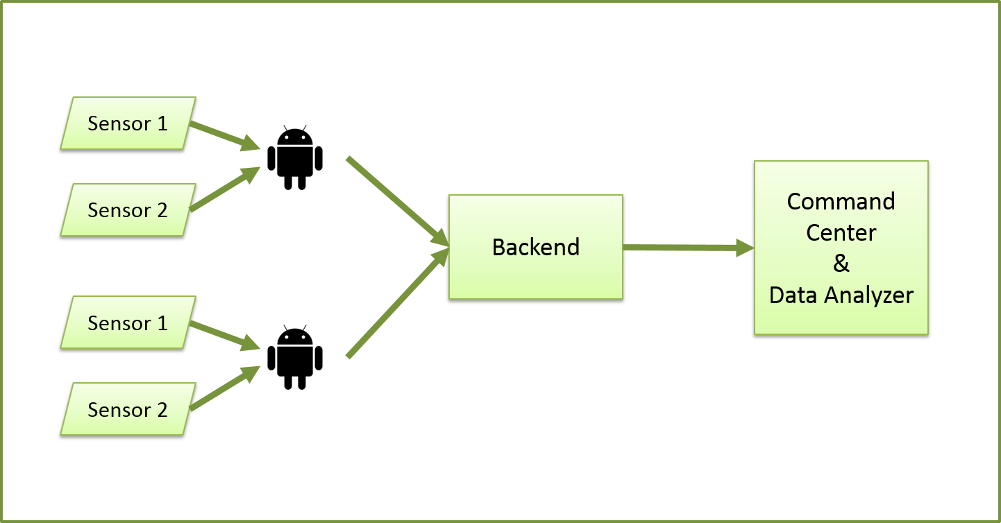
The backbone of the system is its backend messaging component, responsible for being a bridge between all other elements of the system by overseeing how data is transmitted between them. It consists of a C# console application that runs indefinitely as long as the system is active, as well as a server for third-party messaging middleware called RabbitMQ.
RabbitMQ is an asynchronous implementation of the AMQP messaging protocol standard, and is designed to orchestrate transmission of messages between publishes and consumer queues where they can be read in a first-in-first-out manner.
All components entering the system (the control center and all individual units) must sign in via a handshake with the backend before they can enter the system; this adds security by helping to prevent any unauthorized information from being passed between system components. Login information for all components is stored in a server-side database; once a component's information has been verified, they are assigned sending and receiving keys for a RabbitMQ exchange.
An exchange, in RabbitMQ parlance, is a central hub or bus, analagous to a post office, through which messages are routed to the recipients for which they are earmarked. In the case of our system, the middleware does an intermediate route of the message to the C# portion of the backend, where it is further parsed for its destination, message type, and content before being forwarded on, to add extra security that messages are sent in a valid way from valid senders to valid recipients.
Control Center
What the mission control center sees
Control Center:
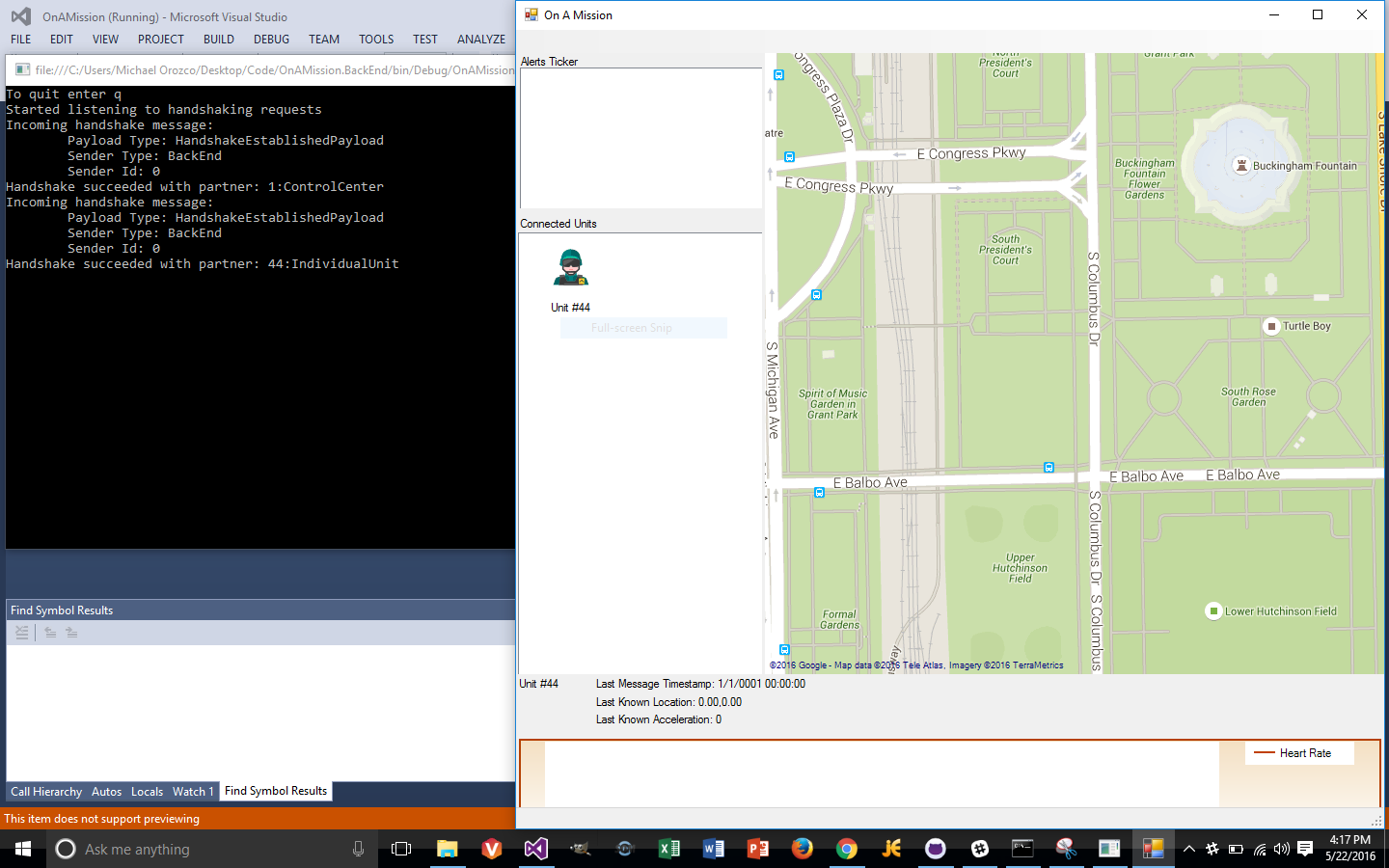
A mission using the software is orchestrated from the Control Center, an executable application which provides a visual representation of data
received from each individual unit. Like individual units, the control center must authenticate before it can receive information routed from the backend.
Once authenticated with the system, the user receives a map view (showing GPS locations of all units), as well as charts for monitoring vital signs from each
unit's health monitors. The control center users can also send data to the individual units as either text messages or graphical signals to indicate
to the soldiers important information about the area in which they are operating.
Hardware
Our hardware setup for this mission
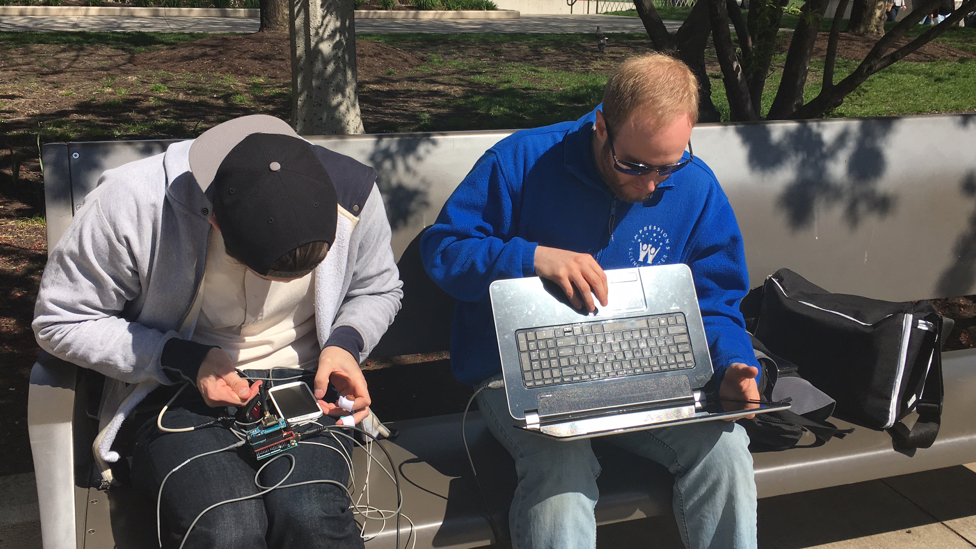
Hardware in action
2 team members testing in the field
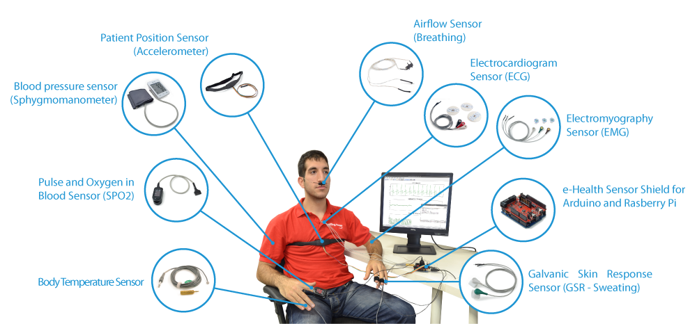
Sensor setup
Soldiers would wear multiple sensors tracking their heart rate, body position, sweat levels, airflow levels and body temperature
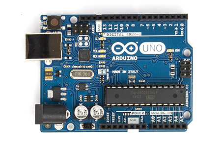
Arduino Uno
This retrieved all sensor data and relayed it to the Android
Our hardware is the key part of the soldiers arsenal in the field. It consists of several sensors connected to an arduino. The arduino is fit with an e-health sensor that pulls data from the sensors and uses a
bluetooth shield to transfer that data to the Android device. The arduino software was created in C and utilizes the e-health API to work with the sensors. Before soldiers head on a mission, the devices are paired
via bluetooth. During missions, the arduino will constantly push updates to the Android with no interaction required from the soldiers.
Analyzer
See how our data is rapidly analyzed to provide immediate updates to command center
The analyzer module can be thought of as the “brains” of the system. If you think of the whole project as being centered around live updates with each module performing some task related to that, then the task of the Analyzer is to rapidly examine live updates in search of specific patterns in the data. Each of the patterns searched for represents a different, undesirable condition.
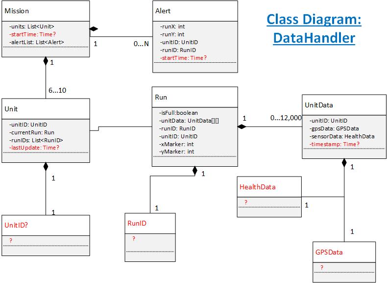
The basic structure of the Analyzer is relatively straightforward. The namespaces are largely descriptive of their functions: the DataHandler namespace contains objects whose hierarchy form a container for the live updates, the AnalysisController namespace and its subspace AnalysisThreads contain the logic for examining the live updates in a multithreaded manner, and the Alerts namespace contains objects to encapsulate relevant data for an emergent condition. The whole module acts as an attachable component of the Control Center. In live update terms the general flow is for the Control Center to receive updates from the backend, which it will then share with the Analyzer. Once the Analyzer identifies a condition it generates an Alert object and passes that to the Control Center.
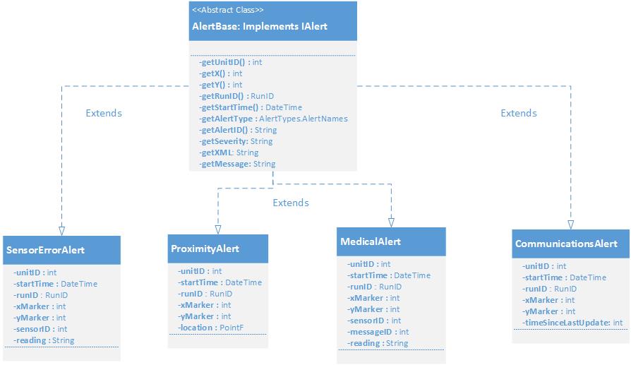
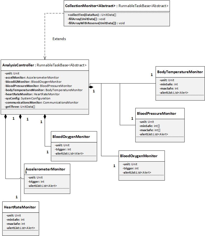
A correlation exists between the Analyzer, its Alerts, and the specific health sensors used by Individual Units. Each Individual Unit connected to the system has a Unit object to store the state of its updates, and each of those Unit objects contains an AnalysisController, which coordinates the creation and destruction of a monitor for each sensor, as well as a CommunicationsMonitor designed to watch for excessive latency or outright disconnections. The Alerts that can be generated fall into four categories. Sensor data that indicates any number of medical issues raises a Medical Alert, Communications delays raise Communications Alerts, abnormal sensor data raises Sensor Error Alerts, and the Mission object contains a ProximityMonitor that raises an alert when GPS data indicates a unit is no longer with the group.
Finally, there are some important features of the Analyzer to help it handle real world conditions. Occasionally, the health sensors will send erroneous data to the Android device. In order to compensate for this, along with any other unforeseen conditions that might cause updates containing “bad” data, the Analyzer requires a condition to persist for three consecutive updates (when applicable) before raising an Alert. In anticipation of long missions that could produce tens of thousands of updates, both processor and memory efficiency had to be accounted for. This was accomplished by storing a given Unit’s updates in a two dimensional array. Once the two dimensional array fills up the data it contains is written to disk and a blank array is created for future data. In this way a minimum efficiency is assured. Additionally, the Alert thresholds are configurable through an XML file, and when the Analyzer is shut down it writes the state of the Mission object to disk so it can be used for debriefing, training, or intelligence purposes.
Analyzer Alerts
Analysis Controller
Analyzer Early Concept Model
Android Individual Unit Setup
Each member of the squad on a mission deployment is equipped with a visor, health sensors, and an android device to assist in completing mission parameters. In this section, the android device will be discussed, and in particular, the Tactical Unit application. Developed using the Android Studio IDE, the application can be installed in any android device running on the Android 4.1 (Jelly Bean) platform or newer. It consists of two main screens: the Login screen and the Home Screen. The Login Screen is used to initiate the handshake sequence between the unit and the backend system to establish an appropriate level of security. Upon exchange success, the unit loads the home screen, where most of the functionality is available to the user.
The Home Screen provides a multitude of buttons and informational segments to assist in the completion of the mission, mainly by serving as a relay system between a soldier’s health sensors and visor and the control center monitoring the welfare of said soldier. The following is a list of the various functions of the application:
GOING DARK BUTTON
Allows soldier to temporarily break the link to the control center as a measure of security. This feature is part of a set of future enhancements for the application.
LOCATION/VITALS DISPLAY
Provides a visual presentation to the soldier as to the location and health sensor readings. These values are continuously sent to the backend in order to monitor the well-being of the soldier.
LOGOUT
Provides the user (soldier) the ability to securely initiate a log-out procedure, severing the connection to the backend, allowing the control center to register an intended disconnect, as opposed to an unwanted link break.
ALERT
This is an emergency signal available to the soldier in times of duress, when possibly only the pushing of a single button is all that can be done, but it alerts the control center of a soldier’s worsening condition while on a mission. This is also a future enhancement.
SEND TEXT
An individual unit will have the capability to communicate with the control center via text message, in order to accurately convey mission conditions or ask for specific instructions.
Send VL / Start/Stop Sim(s)
The application can manually send location and vitals information in order to test functionality and connection with the backend/control center. It can simulate health sensor information and forward it, along with latitude and longitude coordinates, back to the control center to be analyzed.
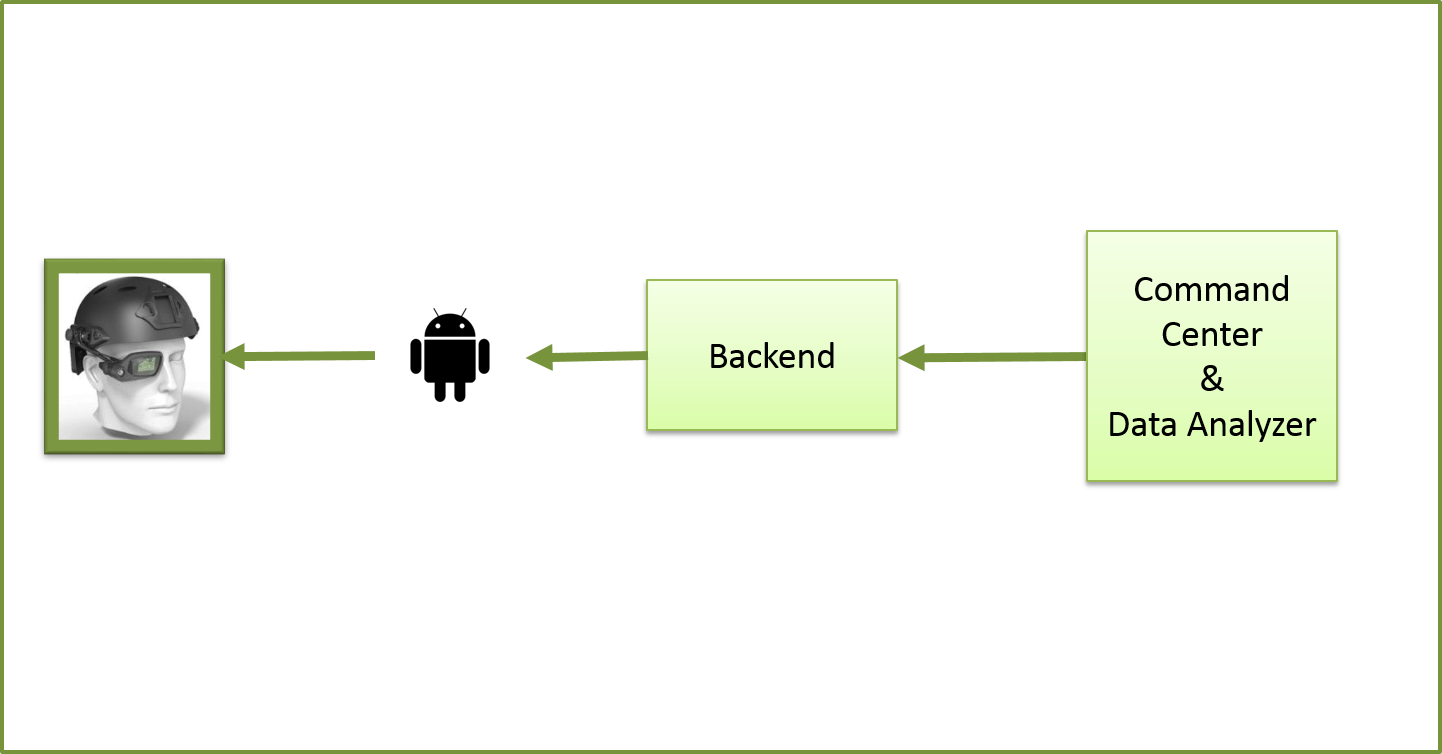
CURRENT TACTICAL DIRECTIVE
Another visual presentation to assist the soldier, this displays directional instructions sent from the control center, in the form of color and signal-coordinated arrows, informing the soldier of the location (direction) of either Friendly Forces, Environmental Conditions, Task Directives, or known Enemy Forces.
POPUP MESSAGE
The Individual Unit can also receive more precise or direct instructions via a text message sent from the control center, in the form of a pop up message at the bottom of the screen.
The application makes use of the android device’s built in Global Positioning System to retrieve the location coordinates, which means the device must maintain a constant connection to the Internet. Vitals information, which includes Heart Rate, Body Temperature, Blood Pressure, Body Oxygen and Accelerometer information, is captured by the android device from the health sensors via Bluetooth technology. Directional directives are relayed by the unit to the Visor by a physical connection, via an HDMI/USB cable.
Due to time constraints and hardware unavailability, full visor integration was not completed by the end of Sprint 3. Visor units were to be modified to encompass only one lens. The major goal of Sprint 4 is to fully implement the modified visors with the appropriate HDMI cable and USB connection to the android device and be able to relay the Current Tactical Directives and text messages.
As a higher level of security beyond the handshake mechanism, an encryption protocol is to be implemented on the message structure between backend/control center and individual units to further deter security breaches, increasing soldier welfare on the battlefield and increasing likelihood of completion of mission objectives.
Enhance the logging capabilities of the system to be able to capture all discernable mission events, allowing for more in-depth analysis of the task completion and
system performance as a whole and at a discreet unit basis.
As mentioned in the Individual Unit sections, future enhancements to the android application will be to incorporate a ‘Going Dark’
feature, which allows the soldier to temporarily disconnect from the system, as would be necessary in the case of a possible system infiltration. Additionally,
an emergency distress signal, in the form of a single button activation, would alert the control center of impending danger or possible incapacitation to the soldier.
Battery power conditions of the android device is another enhancement that will be vital to the performance of the unit,
as it will allow the control center to monitor power levels and make strategic decisions accordingly.
User interface improvements are planned for Sprint 4 for both the Control Center and Android Application.
Cleaner and more user friendly displays will enhance user experience, increasing system performance and efficiency. Android application installation packages will allow for more adaptable display structures.
Safety Case
How the projected kept the mission safety critical
As our software will be responsible for the behavior and safety of teams in life-or-death situations,
we paid strict attention to the implications of various threats to the system and ways in which we could mitigate those threats.
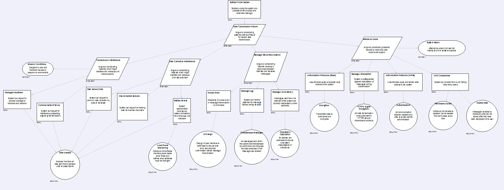
Ultimately we noted four main categories of necessary threat resolution
This refers to threats which might interfere with the actual transmission of data between individual units and the backend.
These threats were generally deemed to be mitigated by the analyzer system,
which registers data that does not make sense or is missing and can alert users to the possibility of interference.
This refers to threats which might interfere with the process of recording information from units in the field (i.e. health sensors and GPS location).
These threats were also primarily addressed by the analyzer,
although we also plan to add power monitoring in a future sprint to address the possibility of lost data due to individual unit battery failure.
This refers to threats which might cause the meaning of messages to be lost or garbled on either the sending or receiving end, or during transmission.
These were addressed with UI design choices to mitigate human error, timestamping to improve message context,
and calibration of all components so that the meaning of messages is always consistent.
This refers to external threats by hostile users intending to interfere with an intended mission.
These were addressed by data encryption, the handshake API used by the backend to verify connections, and volatile,
easily revokable connections that leave no sensitive data stored on the individual units.
Installation Instructions
Backend (Code in folder: Code\OnAMission.BackEnd and Code\OnAMission.WebApi)
Setup a website accessible via HTTP on port 80 and deploy the web app: OnAMission.WebApi
Setup RabbitMQ (Special Instructions?)
Control Center (Code in folder: Code\OnAMission.ControlCenter)
Update OnAMission.ControlCenter.exe.config with the backend URL (or do that before compilation in Settings)
Individual Unit (Code in folder: Android\TacticalUnit)
2 updates in Android\TacticalUnit\app\src\main\java\edu\depaul\studio\on_a_mission\messages\RabbitMQConnection.java
Line 93: change to use the IP or domain of backend
Line 99: change the IP to match the IP or domain of backend
System Requirements
Backend
Publicly accessible IIS with support to ASP .NET MVC 4.0 or higher